The truth table for D flip flop is essential for anyone learning about sequential digital circuits. A D flip flop, or D FF, is a fundamental building block in digital electronics used for storing and transferring data on clock edges.
In this article, we explore the D FF truth table, the excitation table of D flip flop, and the characteristic table of D flip flop to provide a comprehensive understanding of its operation.
Table of Contents
What Is the Truth Table for D Flip Flop?
A D flip flop truth table serves as a simple but powerful reference for understanding how this device responds to changes in its data input and clock signal. Before diving into more complex timing diagrams or circuit applications, the truth table provides a clear snapshot of how the flip flop stores information and when it updates its output. This foundation is especially useful for beginners learning sequential logic and for designers verifying clocked digital systems.
The truth table for D flip flop illustrates the relationship between the input, clock, and output. Unlike simple logic gates, flip flops are edge-triggered devices. The output changes state only at the triggering edge of the clock signal, usually the rising edge.
- On the rising edge of the clock, the output Q follows the input D.
- When there is no clock edge, the output holds its previous state.
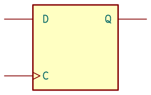
This simple table, shown below, forms the core behavior of the D flip flop and helps in designing synchronous circuits. The D Flip Flop symbol is included below, and shows the edge triggered clock input C, the D input, and the Q output.
| Clock Edge | D (Input) | Q (Next State) |
|---|---|---|
| Rising | 0 | 0 |
| Rising | 1 | 1 |
| No Edge | X | Q (No Change) |
Understanding the D Flip Flop Excitation Table
The excitation table for a D flip-flop explains what input is required to move the flip-flop from its present state to the desired next state. Unlike a truth table that shows outputs, the excitation table shows requirements, making it particularly important when designing sequential circuits using state machines. It helps engineers determine which input values are necessary to implement transitions between states, simplifying the design of counters, finite state machines, and control logic.
The excitation table of the D flip flop helps designers determine the required input values to achieve a desired transition from the current state to the next state . The table shows that the D input directly sets the next state of the flip flop, making the D flip flop easy to use in memory and data storage applications.
| Current State () | Next State () | D Input Required |
|---|---|---|
| 0 | 0 | 0 |
| 0 | 1 | 1 |
| 1 | 0 | 0 |
| 1 | 1 | 1 |
Characteristic Table of D Flip Flop
The characteristic table captures the fundamental behavior of the D flip-flop in a compact form by expressing the next-state function directly. It links the present state and the input D to the resulting next state using a simple expression: Q(next) = D. While this seems straightforward, the characteristic table is extremely useful in digital circuit design because it provides a predictable model of how the flip-flop behaves, making it easier to analyze sequential logic and verify timing and stability conditions.
The characteristic table of D flip flop is a concise way to summarize the output based on the inputs, confirming the flip flop’s functionality. The characteristic table confirms the direct connection between input D and the output after the clock edge. This simple table is shown below.
| D | Q (Next State) |
|---|---|
| 0 | 0 |
| 1 | 1 |
Tips for Truth Table for D Flip Flop
When working with a D flip-flop truth table, it helps to think in terms of state transitions rather than raw input/output combinations. This mindset makes patterns easier to see, especially when comparing the D flip-flop to other types like JK or T flip-flops. Keeping track of the clock edge is also vital, inputs only matter at the trigger moment, so always check whether your specific device uses rising-edge or falling-edge triggering when reading or constructing a truth table.
- Remember that the output only changes on the clock’s triggering edge; it ignores changes in D at other times.
- Use the excitation table to design logic that feeds the correct input for desired output transitions.
- Simulate the flip flop operation with a waveform to better understand timing and edge-triggered behavior.
- Combine the D flip flop with other sequential circuits to build registers, counters, and memory elements.
Did You Know About the Truth Table for D Flip Flop?
Before analyzing the D flip-flop deeply, it’s useful to understand that this device is considered one of the most predictable and stable flip-flops thanks to its direct mapping of input to output. This simplicity is a major reason it forms the basis of registers, pipelines, and memory elements. Many synchronous digital systems rely almost entirely on D flip-flops because their truth table is easier to work with than that of JK or T variants.
- The D flip flop was invented to eliminate the race condition problem seen in SR flip flops.
- It’s widely used in registers, shift registers, and memory devices in computers.
- The excitation table concept applies to other flip flop types (JK, T) but differs in input requirements.
- D flip flops are fundamental components in synchronous digital systems because of their predictable output timing.
Frequently Asked Questions About the Truth Table for D Flip Flop
This section explores some of the most common questions learners have when studying D flip-flop truth tables, offering clear explanations that connect theory to practical applications.
What is a D flip flop used for?
A D flip-flop is mainly used for data storage, synchronization, and timing in digital circuits. It captures a single bit of information at the moment of a clock edge and holds that value until the next triggering event. Because its behavior is so predictable, D flip-flops are essential building blocks for shift registers, counters, memory buffers, latches, and pipelines in digital processors. They ensure data moves cleanly from one stage of a circuit to the next without glitches or race conditions.
How does the D FF differ from other flip flops?
The primary difference is simplicity: the D flip-flop has one input (D) and its next state is always equal to that input on the active clock edge. In contrast, JK flip-flops have toggling behavior and multiple input conditions, and T flip-flops toggle state only when T = 1. This makes the D flip-flop more intuitive and predictable, reducing design complexity. Its truth table is also significantly simpler, which is why it dominates real-world digital design.
What is an excitation table in flip flops?
An excitation table shows the input values required to move a flip-flop from its present state to a specific next state. For the D flip-flop, the excitation table is extremely simple because the required input always matches the desired next state. However, for JK or T flip-flops, the excitation table is more complex and essential for designing state machines or implementing precise state transitions.
Can the D flip flop hold its state?
Yes. If the input D remains the same or the clock does not trigger, the D flip-flop will continue to hold the previously stored value indefinitely. This ability makes it a fundamental storage element in registers and memory units. Holding state reliably is one of the key properties that allows flip-flops to maintain data between clock cycles.
Is the truth table for D flip flop different from other flip flops?
Yes. The D flip-flop truth table is simpler because there is no toggling or multiple input combinations to evaluate. The next state always equals D on the clock edge. Other flip-flops like JK, SR, or T have more complex truth tables with more conditions and special cases (such as “invalid” or “toggle” states). This simplicity is a major advantage in synchronous digital circuit design.
Conclusion
The truth table for D flip flop is a fundamental concept for understanding how data is stored and transferred in digital circuits. By mastering the D FF truth table, excitation table of D flip flop, and the characteristic table of D flip flop, beginners and professionals alike can design reliable and efficient synchronous systems. The D flip flop’s simple yet powerful behavior makes it an essential building block in modern electronics.
See our truth tables category for more information on various truth tables for other logical elements and gates.